Insulation Measurement
Basics
An insulation resistance test is a method by which the security and proper functionality checks of electrical equipment and appliances is examined. It is necessary that all of the conductors, switches, and above all the safety devices are insulated by materials and have a very high electrical resistance so that the current flows in the amount intended for the conductors. Insulation measurement is necessary because of the deterioration of insulation properties of the materials due to environmental influences, as well as stresses over time. With the insulation measurement, the quality of the insulation is checked. Insulation measurement should be carried out not only at start-up and after repair of an electrical installation, but also at regular intervals after commissioning. Thus it can be determined in advance, when the insulation deteriorates and becomes a danger. For commercial installations regular insulation measurement is required.
 Performing an insulation resistance test
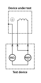
To the test object, a direct current ( DC) is applied, which is much lower than the breakdown voltage. A DC voltage is used to rule out capacitive loads.
The amount of the measured voltage must correspond to at least the amount of the operating voltage. The measurement is performed in the order of the protective conductor (PC) to neutral (N) and protective earth against all external lines (L1, L2, L3).
The effluent stream about the test object is measured, and the result is specified in kOhm, milliohms or TΩ. The measurement is based on Ohm’s law U = R * I. The measurement is non-destructive in the normal case and is performed with an insulation tester (also known as a Megohmeter).
The result of the measurement is influenced by a number of factors (for example temperature, humidity).
Connection charging current – current absorption – leakage current
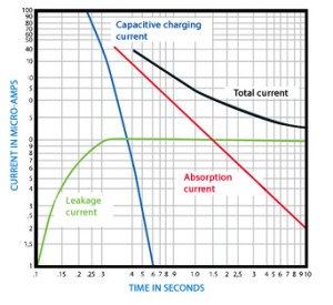
The current flowing through the insulation body current is in this case composed of 3 components:
Capacitive charging current
 The capacitive charging current flows through the capacitance of the insulation has charged up to the applied test voltage. It is initially very high and then decreases exponentially to a value close to 0. A few seconds after the start of the measurement of the capacitive charging current is negligible.
Dielectric absorption current
It flows so that the molecules within the dielectric- of which the insulator consists – reorient the electric field and plays a role for longer than the capacitive charging current. The absorption current reaches 0 after a few minutes.
Actual leakage current
The leakage current flows through the insulator, making it a value for the quality of the insulation. It does not change during the measurement and is also called leakage current.
Since the total current is composed on the test object from the three sub-streams, it decreases strongly with ongoing time measurement.
Measurement methods
Punctual or short-term measurement
Method with evaluation of the temporal evolution
Polarization Index (PI)
Dielectric Absorption Ratio (DAR)
Process with a gradual increase in test voltage

