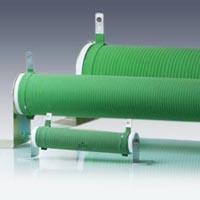
Brake resistor
Brake resistors are of great importance in many electrically powered machines. They operate during start-up and are designed to protect the traction motor from damage. The brake resistor is installed to limit the current in the motor, which regulates the level of electrical activity, and thus protects the engine. This is regulated by what is known as a cruise switch, which is why brake resistors are sometimes referred to as rolling resistance. For generators, this form of resistor also provides the necessary protection from excessive voltages generated by induction. At the same time, the rotational speed is reduced by the current, which results in the vehicle slowing down.
Starting Resistors
The use of mounted starting resistors is quite similar. Here the brake resistors may be attached to the roof, resulting in the heat being dissipated; which provides sufficient cooling. In some types of locomotives the same results are achieved by fixing the starting resistors in the passenger compartments. Primarily used as brake resistors they are also used for temperature control in the winter, to keep the compartments warm. Modern vehicles combine the use of the braking resistors with a heat exchanger, which has the advantage that temperature regulation is not affected by the operation of the brakes.
Frequency Inverter and Brake Resistor
There has been research carried out over a long period of time to improve the braking resistors in order to achieve better results. For this reason frequency inverters and power settings are mostly used nowadays
. The first one enables the conversion of current and the second one can be regulated to produce the maximum amount of power. This is achieved through the use of a thyristor. A better control of the current strength is achieved when the fluctuations in the mains supply are removed. During subsequent braking, power can be fed back into the mains supply. Resistors also feature in electromotive braking. They provide a considerable advantage as they allow safe breaking, even when there are connection problems with the mains network.
The brake resistors work properly, but only under certain conditions. Primarily there is a need for constant cool air. In addition, the heated air must be able to vent freely. Also, when the ambient temperature reach
es 40°C or more, it needs to be cooled. These criteria need to be maintained in all cases to avoid damage to the braking resistors and other components which may occur. To summarise, the brake resistor can be said to be making a major contribution to the smooth operation of machinery.
Brake Resistor Power
Calculation based on a 55 kW inverter:
P = Q * Kc = 55 kW * 20% = 11 kW
Q = motor power
Kc = the ratio of energy recovery during engine operation (depending on load)
Some key Kc values:
| Centrifuge | 05%-20% |
| Lifts | 10%-15% |
| Cranes (<100m) | 20%-40% |
| Oil Field Pumps | 10%-20% |
| Other | 10% |
Resistance Value
R = 2 * U / I = 2 * 670 V / 110 A = 12 ohms
U = operating voltage during brake application (DC link voltage)
I = operatin current during brake application

